IMAGEN DE REFERENCIA
Existen artículos en su cotización.
Precios totales :
Di algo..
Sin resultados, re intente de nuevo
Navegador incompatible


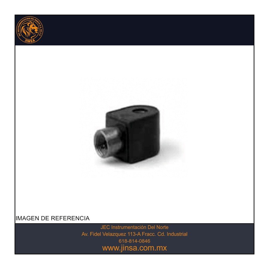
Bobina apexplosion integrada 120/60 - 110/50 V CA 10W tipo h ap
FICHA TECNICA

¿Necesitas certificado de calibración?, ¡pregunta a tu vendedor favorito vía WhatsApp!
| Part Number | Type of Termination* | Voltage | Wattage | Class |
| H222P3 | UL Hazardous Locations NEMA Type 7/9 w/ 18" Leaded Coil | 120/60, 110/50 | 10 | H |
General Description:
Solenoid Enclosure and Coil Information Coils are electrical devices that produce magnetic flux when electrical power is applied to the windings.
Surrounding the coil is the metal solenoid enclosure and frame. Together with the plunger and stop, it forms the magnetic circuit that operates the valve.
Without the enclosure, the magnetic circuit is not complete. Without a complete magnetic circuit, the magnetic field is reduced and valve performance suffers.
Depending on the coil voltage and power rating, the pressure rating of the valve can vary.
Solenoid enclosures come in a variety of constructions offering varying levels of protection against the elements and other forces. NEMA identifies the different
enclosures as “Types” and NEC sets standards for their safety and performance.
Integrated coils have an epoxy or thermoplastic "over-molding" creating a one-piece coil/enclosure for modularity and protection from the environment.
The National Electrical Manufacturers Association (NEMA) recommends suitable materials and components to meet each enclosure type. The enclosures
listed here will only meet the applicable NEMA recommendations when properly installed and operated to NEMA specifications and in accordance with the NEC.
Electrical Characteristics:
Standard Voltages:
AC – 24/60
120/60 110/50
240/60 220/50
DC –12, 24 &120
For other Voltages – Consult Factory
Coil Classification:
Class F Standard
Class H Available
Agency Approvals:
Standard valves with NEMA Type 4X or Explosion Proof solenoid enclosures are UL Listed and CSA Certified.
DIN coils are UL Recognized. For additional details, consult factory. Optional coils feature ATEX and IECEx Approvals.
Ultra Low Power Coils (Coil Chart 12)
are used on valves with a unique solenoid operator designed to keep current draw to a minimum, thus achieving the extremely low power consumption of 0.6 watts
with no refresh time required for subsequent energization. These valves are ideally suited for use in automated control systems, applications where minimizing
energy consumption is critical or where heat rise in the coil must be kept to a minimum. Due to the low power consumption, an increased number of solenoid valves
can be driven from the same power source, reducing the overall installation cost.
Power and Voltage
All coils used in Parker FCD solenoid valves are designed for continuous duty except where noted.
On AC, inrush current occurs at the moment the solenoid is energized. The continuous current after
inrush is holding current. Typical AC current values are shown to the right. DC solenoids have no inrush.
Typical amp ratings for DC are determined by dividing DC watts by DC voltage.
All Parker FCD solenoid valves are tested to operate at 15% undervoltage and full pressure ratings. AC
and DC voltage ratings (nominal) and normal operating ranges, as shown in the following table, are standard.
For special voltages, consult the factory.
AC/DC Voltage Range
All coils used in Parker FCD valves are designed for continuous duty except where noted.
They can remain energized continuously without damage from overheating or mechanical failure.
AC and DC voltage ratings (nominal) and normal operating ranges, as shown in the following table, are standard.
All coils used in Parker FCD solenoid valves are either Class “F” or Class “H” molded epoxy, and are constructed in
accordance with UL, IEEE, NEMA and other accepted standards
Envíanos un WhatsApp
Contacto vía:


